|
1
|
|
|
2
|
- Designs considered
- Decay channel with chicane
- Decay channel with phase rotation, cooling
- Tracking code
- Optimisation approach
- Results
- Future work
- …and issues still to be solved
|
|
3
|
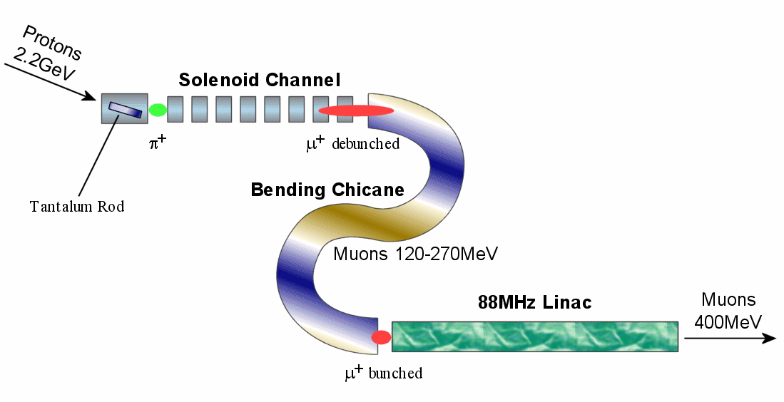
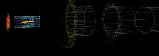
- Pion to muon decay channel
- Accepts pions from the target
- Uses a series of wide-bore solenoids
- “Phase rotation” systems
- FFAG-style dipole bending chicane (2001)
- For short bunch length à
400MeV muon linac
- 31.4 MHz RF phase rotation (2003)
- For low energy spread à
ionisation cooling ring
|
|
4
|
- Challenge: high emittance of target pions
- Currently come from a 20cm tantalum rod
|
|
5
|
- Challenge: high emittance of target pions
- Currently come from a 20cm tantalum rod
|
|
6
|
- Challenge: high emittance of target pions
- Currently come from a 20cm tantalum rod
- Solution: superconducting solenoids
- S/C enables a high focussing field
- Larger aperture than quadrupoles
- Basic lattice uses regular ~4T focussing
- Initial smaller 20T solenoid around target
- 30m length = 2.5 pion decay times at 200MeV
|
|
7
|
|
|
8
|
- 31.4MHz RF at 1.6MV/m (2003 design)
- Reduces the energy spread 180±75MeV to ±23MeV
- Cavities within solenoidal focussing structure
- Feeds into cooling ring
|
|
9
|
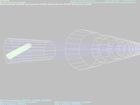
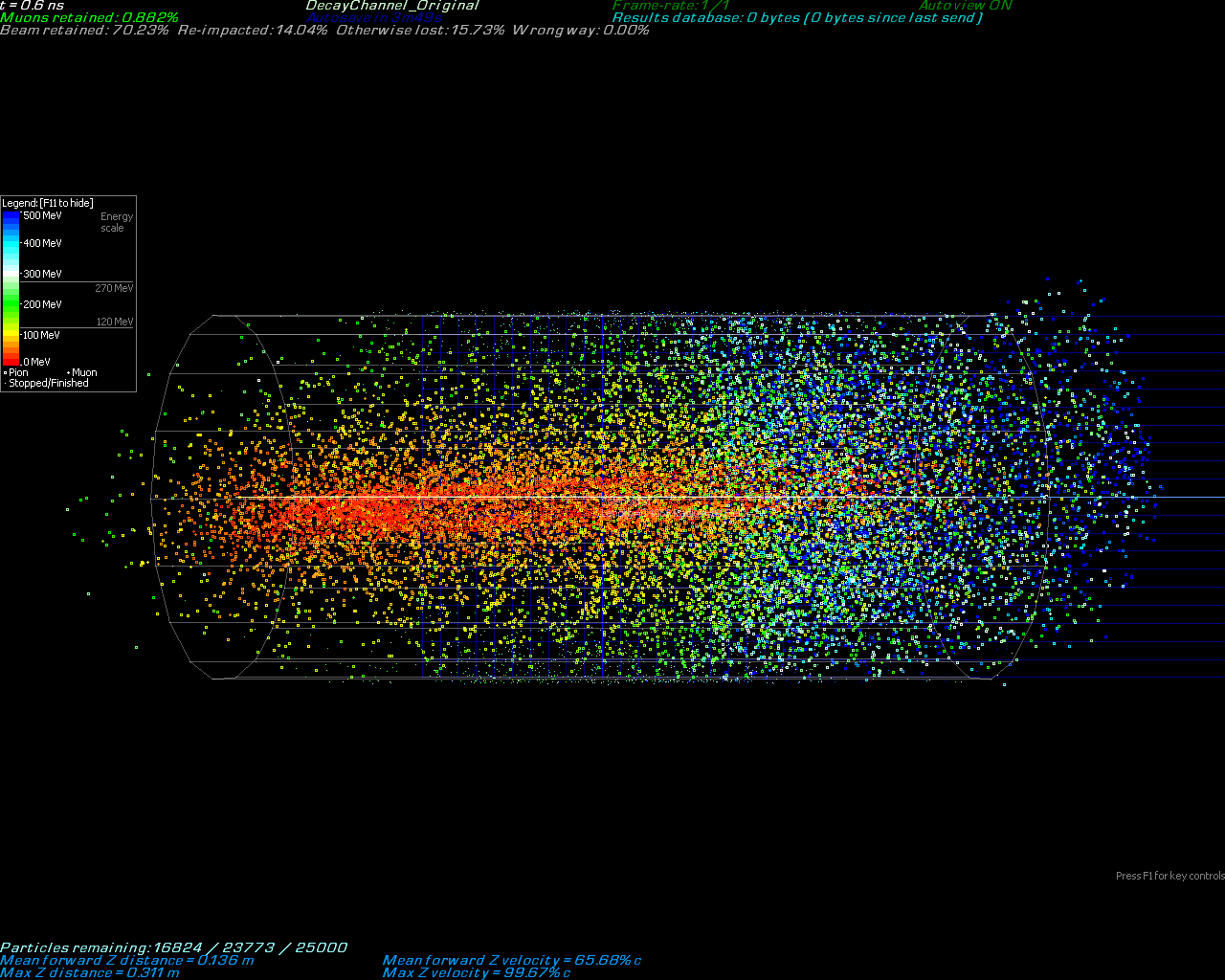
- Non-linearised 3-dimensional simulation
- PARMILA was being used before
- Uses realistic initial p+ distribution
- Monté-Carlo simulation by Paul Drumm
- Particle decays with momentum kicks
- Solenoid end-fields included
- OPERA-3d field maps used for FFAG-like magnets in chicane (Mike Harold)
|
|
10
|
- Typically use 20k-50k particles
- Tracking is done by 4th order classical Runge-Kutta on the 6D
phase space
- Currently timestep is fixed at 0.01ns
- Solenoids fields and end-fields are a 3rd order power
expansion
- Field maps trilinearly interpolated
- Particle decays are stochastic, sampled
|
|
11
|
- How do you optimise in a very high-dimensional space?
- Hard to calculate derivatives due to stochastic noise and sheer number
of dimensions
- Can use a genetic algorithm
- Begins with random designs
- Improves with mutation, interpolation, crossover…
- Has been highly successful so far in problems with up to 137 parameters
|
|
12
|
- 12 parameters
- Solenoids alternated in field strength and narrowed according to a
pattern
- 137 parameters
- Varied everything individually
|
|
13
|
- Chicane is a fixed field map, not varied
- Solenoid channels varied as before
- Both sides of chicane
- Length up to 0.9m now
- RF voltages 0-4MV/m
- Any RF phases
- ~580 parameters
- RF phase rotation
- Similar solenoids, phases (no field map)
- RF voltages up to 1.6MV/m
- ~270 parameters
|
|
14
|
- Decay channel:
- Original design: 3.1% m+ out per p+ from rod
- 12-parameter optimisation à 6.5% m+/p+
- 137 parameters à 9.7% m+/p+
- Re-optimised for chicane transmission:
- Original design got 1.13%
- 12 parameters à 1.93%
- 137 parameters à 2.41%
|
|
15
|
- “Success” is 1021 m+/yr in the storage ring
|
|
16
|
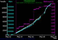
- How do you run 3`900`000 simulations?
- Distributed computing
- Internet-based / FTP
- ~450GHz of processing power
- ~130 users active, 75`000 results sent in last week
- Periodically exchange sample results file
- Can test millions of designs
- Accelerator design-range specification language
- Includes “C” interpreter
- Examples: SolenoidsTo15cm, ChicaneLinacA
|
|
17
|
|
|
18
|
|
|
19
|
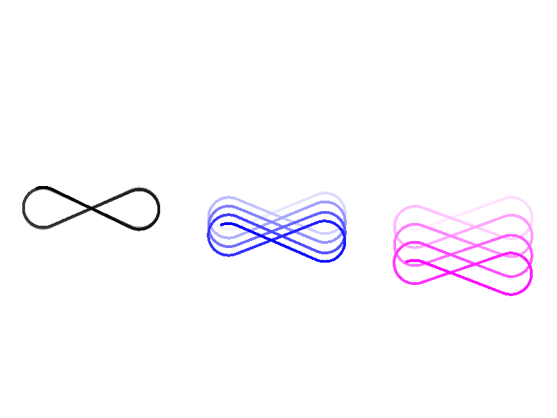
- Original design had alternating (FODO) solenoids
- Optimiser independently chose a FOFO lattice
- Has to do with the stability of off-energy particles
|
|
20
|
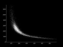
- Nontrivial optimum found
- Preferred length?
- Narrowing can only be due to nonlinear end-fields
|
|
21
|
- Chicane and RF phase rotation designs are starting to be run now
- Initial results promising
- Cooling ring later this year
|
|
22
|
- 10-20 turns
- Uses H2(l) or graphite absorbers
- Cooling in all 3 planes
- 16% emittance loss per turn (probably)
|
|
23
|
- Solenoid field clipping distance
- Need ‘solid’ solenoids for best accuracy
- ICOOL has recently added these
- New target dataset needed for 8GeV
- Trying to get MARS
- Possibility of target energy optimisation
- Code could do with variable timesteps and/or error control
|
|
24
|
- Muon1 modified to count lost particle energies
- For a 4MW p+ beam:
- 35kW deposited in S1 (r=10cm)
- Large >1kW amounts deposited up to S5
- Added “collimators” to the simulation
- Decreases losses to 10’s of watts in all but S1 and S2
- S1 needs enlarging to accommodate an entire Larmor rotation
- Consistent target-area layout is needed
|

 Notes
Notes