|
1
|
- Neutrino factory (2018)
- 4MW proton driver
- p+ à p+
à m+ à e+nenm
- Linear e+e− collider (2014/5)
- Muon collider (2023)
- p+ à p+,p−
à m+,m−
à
- Multi-TeV lepton collision
- and others…
|
|
2
|
|
|
3
|
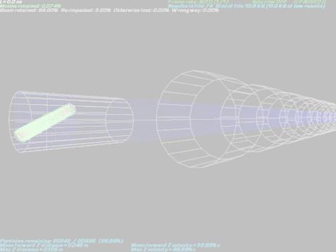
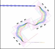
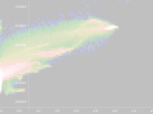
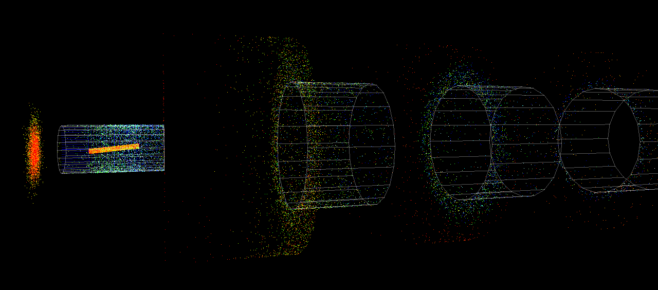
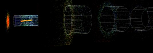
- Nonlinear 3-dimensional simulation
- PARMILA was being used before
- Uses realistic initial p+ distribution
- Monté-Carlo simulation by Paul Drumm
- Particle decays with momentum kicks
- Solenoid end-fields included
- OPERA-3d field maps used for FFAG-like magnets in chicane (Mike Harold)
|
|
4
|
- 12 parameters
- Solenoids alternated in field strength and narrowed according to a
pattern
- 137 parameters
- Varied everything individually
|
|
5
|
- Decay channel:
- Original design: 3.1% m+ out per p+ from rod
- 12-parameter optimisation à 6.5% m+/p+
- 137 parameters à 9.6% m+/p+
- Re-optimised for chicane transmission:
- Original design got 1.13%
- 12 parameters à 1.93%
- 137 parameters à 2.41%
|
|
6
|
|
|
7
|
- How do you optimise in 137-dimensional space?
- Hard to calculate gradient due to stochastic noise
- Use genetic algorithm
- Random designs
- Mutation
- Interpolation
- Crossover
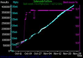
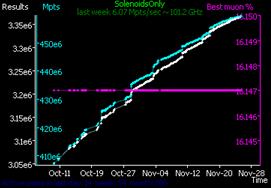
- How do you run 3`700`000 simulations?
- Distributed computing
- Internet-based / FTP
- ~130 users active in last week
- Periodically exchange sample results file
|
|
8
|
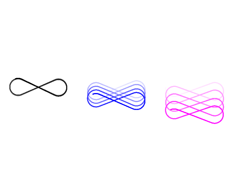
- Original design had alternating (FODO) solenoids
- Optimiser independently chose a FOFO lattice
- Has to do with the stability of off-energy particles
|
|
9
|
- Nontrivial optimum found
- Preferred length?
- Narrowing can only be due to nonlinear end-fields
|
|
10
|
- Muon1 modified to count lost particle energies
- For a 4MW p+ beam:
- 35kW deposited in S1 (r=10cm)
- Large >1kW amounts deposited up to S5
- Added “collimators” to the simulation
- Decreases losses to 10’s of watts in all but S1 and S2
- S1 needs enlarging to accommodate an entire Larmor rotation
- Consistent target-area layout is needed
|
|
11
|
- Decay channel (as before)
- 31.4MHz RF phase rotation
- Reduces energy spread from 190±70 to ±23MeV
- Cooling ring (20 turns)
- Uses H2(l) or graphite absorbers
- Cooling in all 3 planes
- 16% emittance loss per turn?
|

 Notes
Notes